Gridded Areas allow you to calculate building objects such as ceiling or floor tiles, bricks, wall panels, any surface that includes a repeating, rectangular pattern, and you want to account for the pattern (such as the number of tiles, bricks, etc.).
Drawing Gridded Area Takeoff
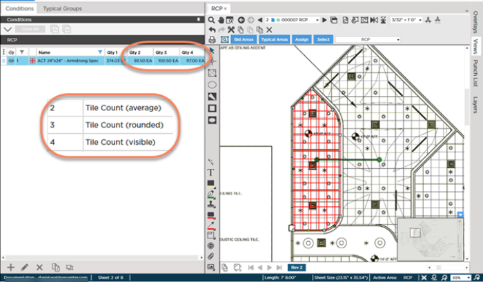
Our example starts with a room with the 3-Point and Rounded arcs. We setup our Takeoff Item to display several "Tile Count" Results so you can see the difference alignment makes - see Related Articles for details on selecting which Area Takeoff Item Results get displayed.
- We start by creating a Takeoff Item setup with a "Grid" - see Related Articles for details on setting up Area Takeoff Items.
- Then, we use any of the previously described Area Takeoff tools to draw your takeoff, see Using Area Takeoff Tools for a refresher on Area Takeoff Tools.
Aligning Gridded Takeoff to Match Plans
In our example, the grid of the takeoff does not match the grid of the plan (the size matches, but the position does not).
Take note of Results 2, 3, and 4 which show Average, Rounded, and Visible Tile Counts.

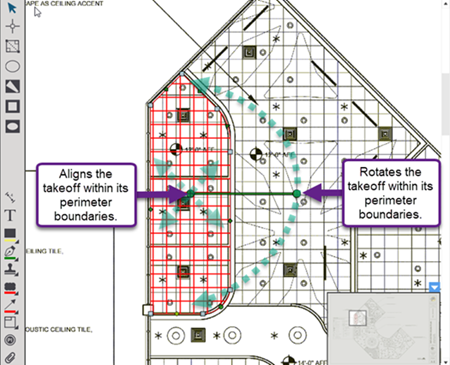
To align the takeoff to the plan, right-click on the object and select "Align to Grid"

Use the move and rotate controls to align the takeoff so it matches the plan.

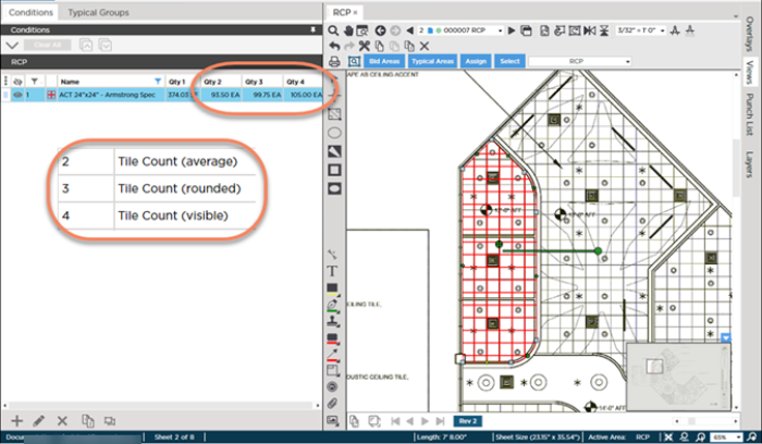
Notice, the "Average" Result does not change because it simply divides the total square foot (or m2) of the object by the square foot (or m2) of a single tile.), however...
Notice the new Tile Count quantities for Results 3 (Rounded) and 4 (Visible)?
Although in our example, those are minor differences, remember, this is just one piece of takeoff and a relatively small one at that. Imagine the difference alignment could make over an entire project or a much larger piece of takeoff.


 Elliptical Area Takeoff Tool